Chinafix Laptop Repair Book , A Professional Maintenance Book [Paper Book]
Laptop repair book, bilingual in Chinese and English.
-
- Price: $80 without shipping cost
- Author: 迅维网(Chinafix.com)
- Paperback: 678 pages
- Language: English&Chinese
- Shipping Weight: 1.5KG
- How to buy, email: pay@laptopschematic.com (Ask the shipping price)
- Paypal: pay@laptopschematic.com
About the author
Xunwei(迅维网 Chinafix.com) is China’s largest community for professional maintenance personnel of computers and digital products, converging domestic maintenance elites to provide detailed maintenance cases and share their experience. Xunwei is mainly engaged in maintenance and assembly of computers, phones and unmanned aerial vehicle, training for driving skills and other relevant business such as training for maintenance, the development and sale of tools and accessories. It provides customers with one-stop service of high-quality technology, accessories, products and excellent staff.
Editorial Reviews
This book is suitable for staff with the basic knowledge of electronic circuit or computer maintenance personnel to read, and more suitable for those who have the experience of maintaining computer motherboard.
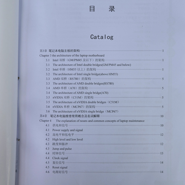
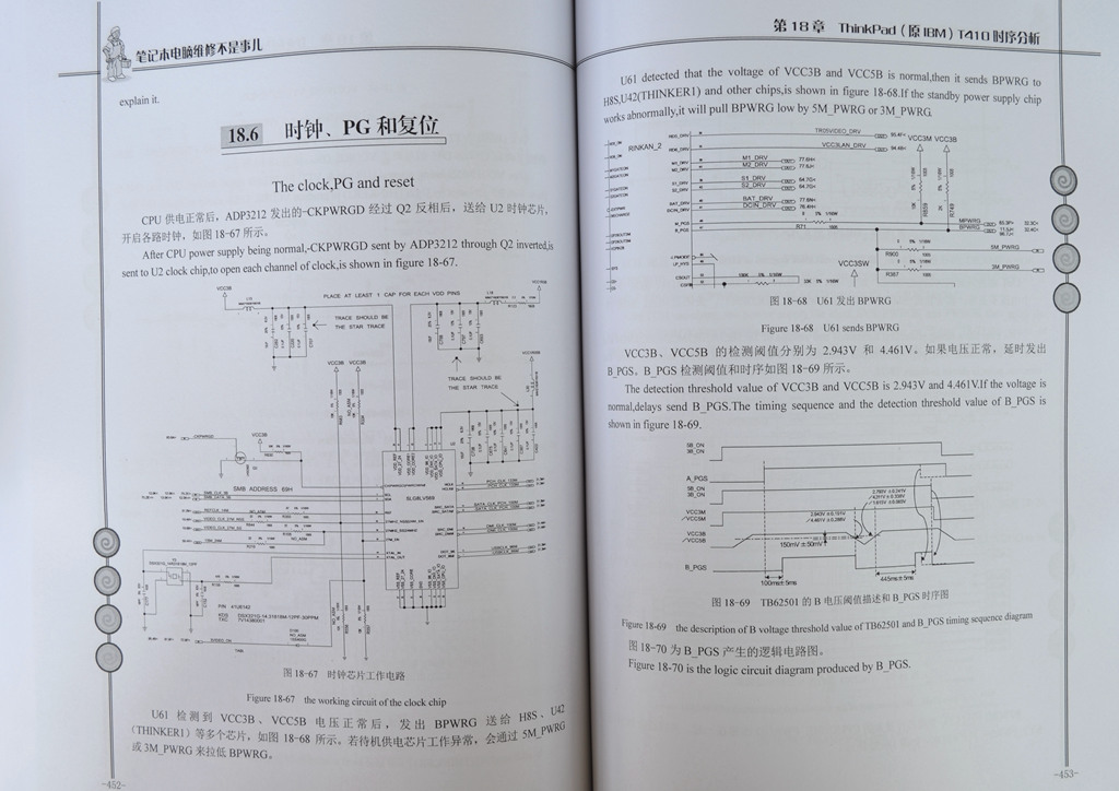
Table of contents
(The book begins with chapter 3, chapter 1&2 have no translation as a basis.)
Chapter 3 The architecture of the laptop motherboard
- 3.1 The architecture of Intel double bridges(GM/PM45 and below)
- 3.2 The architecture of Intel single bridge(above HM55)
- 3.3 The architecture of AMD double bridges(RS780)
- 3.4 The architecture of AMD single bridge(A70)
- 3.5 The architecture of nVIDIA double bridges(C51M)
- 3.6 The architecture of nVIDIA single bridge(MCP67)
Chapter 4 The explanation of nouns and common concepts of laptop maintenance
- 4.1 Power supply and signal
- 4.2 High level and low level
- 4.3 Jump and pulse
- 4.4 Clock signal
- 4.5 Reset signal
- 4.6 Power good signal
- 4.7 Open signal
- 4.8 Chip selection signal
- 4.9 The explanation of the signal name for some manufacturers
- 4.9.1 Wistron
- 4.9.2 Quanta
- 4.9.3 Asus
- 4.9.4 Compal
- 4.9.5 DELL
- 4.9.6 Apple
- 4.9.7 Inventec
- 4.9.8 ThinkPad(IBM)
Chapter 5 The basic application circuit of electronic components
- 5.1 The basic application circuit of capacitance
- 5.2 The basic application circuit of the resistance
- 5.3 The basic application circuit of the diode
- 5.4 The basic application circuit of the audion
- 5.5 The basic application circuit of the field-effect tube
- 5.6 The basic application circuit of the gate circuit
- 5.7 The basic application circuit of the comparator
- 5.8 The basic application circuit of the transverter
- 5.9 The basic application circuit of the voltage regulator
Chapter 6 The use of the circuit diagram and the point bitmap
- 6.1 The use of the circuit diagram
- 6.2 The use of the common point bitmap
Chapter 7 The introduction of EC and BIOS
- 7.1 Working conditions and functions of EC
- 7.2 Functions and working conditions of BIOS
Chapter 8 The basic working process of notebook computer
- 8.1 The general boot process of notebook computer
- 8.1.1 Hard starting process and Intel chipset standard timing
- 8.1.2 The soft start process
- 8.2 About ACPI specification
- 8.2.1 ACPI summarize
- 8.2.2 G(Global) state of ACPI
- 8.2.3 D(Device) state of ACPI
- 8.2.4 S(Sleeping) state of ACPI
- 8.2.5 C state of ACPI
- 8.2.6 the power and the control signal of ACPI
- 8.3 Clock,PWRGD and the reset circuit
- 8.3.1 The clock circuit
- 8.3.2 PWRGD and the reset circuit
Chapter 9 The explanation of PWM circuit
- 9.1 The introduction of PWM circuit
- 9.1.1 The brief introduction of the working principle of PWM
- 9.1.2 The meaning of common English abbreviation in PWM circuit
- 9.1.3 The boot-strap circuit
- 9.1.4 Output voltage regulation circuit
- 9.1.5 The voltage detection circuit
- 9.1.6 The current detection circuit
- 9.1.7 The working mode
- 9.2 Analysis of the standby power chip
- 9.2.1 Analysis of MAX8734A
- 9.2.2 Analysis of TPS51125
- 9.2.3 Analysis of RT8206A/RT8206B
- 9.3 Analysis of the memory power supply chip
- 9.3.1 Analysis of ISL88550A
- 9.3.2 Analysis of RT8207
- 9.4 Analysis of the bridge/bus power supply chip
- 9.4.1 Analysis of the single PWM controller RT8209
- 9.4.2 Analysis of the dual PWM controller TPS51124
- 9.5 Analysis of CPU core power supply
- 9.5.1 The features of CPU VCORE power supply
- 9.5.2 Analysis of MAX8770
- 9.5.3 Analysis of ISL6260
- 9.5.4 Analysis of commonly used chip ISL95831 by HM65 motherboard
- 9.5.5 Analysis of commonly used chip ISL6265 by AMD platform
Chapter 10 Analysis of Quanta computer circuit
- 10.1 Analysis of Quanta CT6 RTC circuit
- 10.2 Analysis of Quanta CT6 protective isolation circuit
- 10.3 Analysis of Quanta CT6 power-on sequence circuit
- 10.4 The analysis of Quanta ZQ5(Acer as4733z) protective isolation circuit
- 10.5 Analysis of Quanta AX1 protective isolation circuit
Chapter 11 Analysis of Wistron OEM laptop circuit
- 11.1 Analysis of Wistron HBU16-1.2 protective isolation circuit
- 11.2 Analysis of Wistron HBU16-1.2 standby circuit
Chapter 12 Analysis of Compal OEM laptop circuit
- 12.1 Analysis of Compal LA_5891P protective isolation and the standby circuit
- 12.2 Analysis of Compal LA-6631P protective isolation circuit
- 12.3 Analysis of Compal LA-6751P protective isolation circuit
Chapter 13 Analysis of Invenyec OEM laptop circuit
- 13.1 Analysis of Inventec DosXX Dunkel 1.0 protective isolation circuit
- 13.2 Analysis of Inventec DosXX Dunkel 1.0 standby circuit
- 13.3 Analysis of Inventec feature circuit
- 13.3.1 Analysis of OCP circuit
- 13.3.2 Analysis of Big OR GATE circuit
Chapter 14 Analysis of Intel PCH sequence(I3/I5/I7)
- 14.1 About Intel ME and Intel AMT
- 14.2 Analysis of Intel HM55 series chipset timing sequence
- 14.3 Analysis of the chipset timing sequence above Intel HM65 series
Chapter 15 Analysis of ASUS K42JR(HM5x) timing sequence
- 15.1 The standby state
- 15.2 Trigger
- 15.3 The boot state
- 15.4 Clock,PG and reset
Chapter 16 Analysis of Apple A1286(HM5x) timing sequence
- 16.1 G3 state
- 16.2 RTC circuit
- 16.3 S5 state
- 16.4 Trigger
- 16.5 S3 and S0 state
- 16.6 The clock,PG and the reset
Chapter 17 Analysis of DELL N4110(HM6x) timing sequence
- 17.1 G3 state
- 17.2 Trigger
- 17.3 The standby and the memory power supply of the bridge
- 17.4 S0 state
- 17.5 PG and the clock
- 17.6 CPU core power supply
- 17.7 Reset
- 17.8 The graphics card power supply
Chapter 18 Analysis of ThinkPad(IBM) T410 timing sequence
- 18.1 G3 state
- 18.2 S5 state
- 18.3 AMT
- 18.4 Trigger
- 18.5 S3 and S0 state
- 18.6 The clock,PG and reset
- 18.7 The battery charge circuit
Chapter 19 Timing analysis of AMD platform
- 19.1 The standard timing sequence of nVIDIA
- 19.2 The explanation of nVIDIA chipset timing sequence(MSI MS_16352)
- 19.3 The standard timing sequence of AMD chipset
- 19.4 The timing sequence of AMD chipset(ACER 4235,Quanta ZQE)
- 19.5 The explanation of AMD A70M(Lenovo G485,Compal LA-8681P)
- 19.5.1 RTC circuit
- 19.5.2 Protective isolation circuit
- 19.5.3 The standby power supply
- 19.5.4 The trigger switch
- 19.5.5 Produce power supply
- 19.5.6 APU power supply
- 19.5.7 Clock,PG and reset
- 19.5.8 The independent graphics working timing sequence
Chapter 20 Analysis of the laptop battery charging circuit
- 20.1 Analysis of charging chip MAX1772 used usually under Intel 965GM platform
- 20.1.1 The name and the definition of the pin
- 20.1.2 Application circuit
- 20.2 Analysis of the charging chip ISL88731 used usually by the above Intel GM45
- 20.2.1 The name and the definition of the pin
- 20.2.2 The typical application diagram
Chapter 21 Maintenance of common failures
- 21.1 Short trouble
- 21.2 Do not trigger fault
- 21.3 Power down fault
- 21.4 Not running fault
- 21.5 The maintenance of common code
- 21.6 The screen shows fault
- 21.7 The sound card fault
- 21.8 USB fault
- 21.9 The network card fault
- 21.10 SATA interface fault
- 21.11 The fan interface fault
- 21.12 Crash fault
Chapter 22 Example of maintenance
- 22.1 The example pf maintenance about don’t boot fault
- Example 1 IBM T61 not boot
- Example 2 Lenovo G480 inflow water,which cause not boot
- Example 3 lightning stroke cause that Lenovo Z360 does not boot
- Example 4 IBM R60 no standby
- Example 5 ASUS A42J multiple fault
- Example 6 ASUS K42JR no standby
- Example 7 Acer Aspire 4738G powered off
- Example 8 ASUS K42JR powered off
- Example 9 SONY NS90HS not boot after lightning stroke
- Example 10 Lenovo Xuri 410M not power on
- Example 11 DELL N4030 I3 not trigger
- Example 12 Toshiba L500 not boot
- Example 13 Samsung R23 not boot
- 22.2 The example of the breakdown maintenance about not bright
- Example 14 Lenovo G460 do not run code
- Example 15 DELL V130 no display after powering on
- Example 16 Samsung R428 no display after powering on
- Example 17 Inventec HP511 no display and powered down after triggering
- Example 18 eMachines D725 inflow water,which cause not light
- Example 19 Lenovo G470 no CPU voltage
- Example 20 Lenovo Y430 no clock
- Example 21 Acer 5750G starting up but not display
- 22.3 The fault maintenance examples of power down
- Example 22 used the oscilloscope to repair the fault of power down of Lenovo G450
- Example 23 Lenovo G550 the standby is abnormal and power down
- Example 24 HP 4411S power down when enter into the system
- Example 25 Acer Aspire 4310 power down
- Example 26 Lenovo Zhaoyang E43G power down after triggering
- Example 27 HP 510 power down repeatedly and restart after starting up
- Example 28 Lenovo V450 power down when starting up
- Example 29 HP 4411 power down repeatedly after starting up
- 22.4 The maintenance examples of other faults
- Example 30 ASUS A8E large short circuit when install battery
- Example 31 Lenovo s10.2 dark screen